We’ve had an incredible winter and Utah this year. Storm after storm have been blessing us with an unforgettable season of back to back powder days, making all that money I spent on my ski pass totally worth it.
As much as I would like to have my favorite resort to myself, that isn’t realistic. Everyone in the general Salt Lake area has to compete for their share of untouched pow. And for me, being over an hour away without traffic, that means I have to wake up way too early to even have a chance at a parking spot. If my car is covered in snow, the 10 minutes I’d have to wait for the defroster to kick in and melt it off the windshield can be the difference between parking right next to the lift or parking on the side of the road a mile away. Anyone who has hiked in ski boots before knows that is definitely not an ideal way to start the day.
This has made it imperative that I find time between classes and my job to finish this project. It’s really nice walking out to my car and only having to brush off the already melted snow before I can pick up the boys and head to the mountains. And once summer rolls around, I won’t burn to death getting into my car if I’d forgotten to turn the AC on before I left.
I’m on a college student budget (and already spent all my money on ski gear), and part of the reason I’m posting this is to show that DIY hardware doesn’t have to be expensive, and that, even on a very limited budget, you can make some really cool stuff. Feel free to replace parts with better more expensive ones, or even design a custom PCB if you have the knowledge for that (and please let me know if you do as I would love to use it)!
Materials
Parts
- Arduino Mega amazon aliexpress search
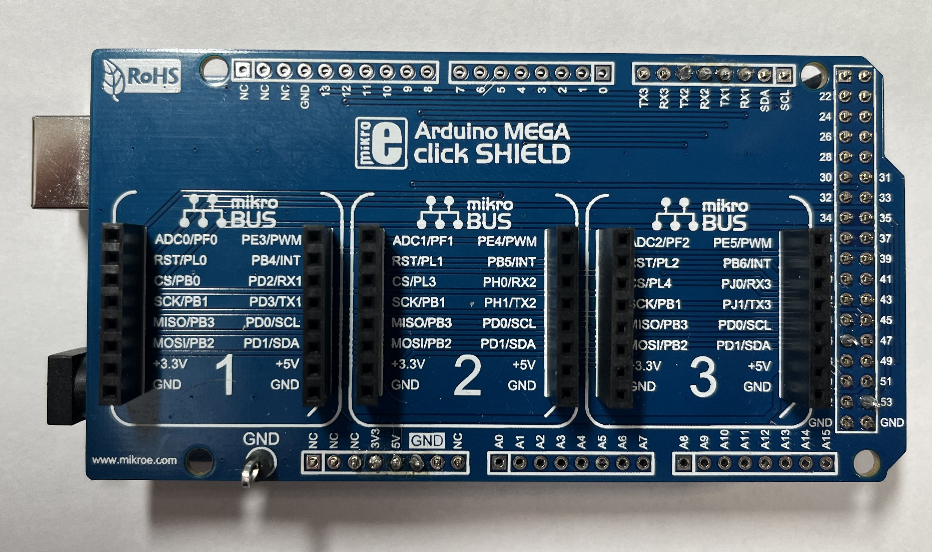
- Mikroe LIN Shield for Arduino Mega mikroe mouser
- 2x Mikroe LIN Click mikroe mouser
- Toyota connectors 90980-12369 and 90980-12370 (get 2 of each because thye’re easy to break) aliexpress
- Protoboard (insert size)
- Dollar store USB car charger
- 18-20 gauge wire
- Gorilla mounting tape (or 3M VHB tape) amazon
Tools
- Soldering kit. Get a good one with a temperature dial; if you try to use a cheap soldering iron from Walmart, you’ll end up very frustrated very quickly. These are expensive so you may want to borrow one. amazon
- Extraction tool for removing wires from connectors (I used a breadboard pin, but they break easily so I wouldn’t recommend it)
- Trim removal tool amazon
- Digital multimeter amazon
Building the Interceptor
Step 1: Assemble the Mikroe LIN Shield
The LIN shield comes with header pins that are not attached, so you will need to solder the ones that you’ll be using. You do not need to solder all of them. Solder pins for:
- ground
- 5V
- serial RX and TX
- the enable pins for both LIN clicks
If you aren’t a soldering expert, you may want to use your multimeter to check continuity between the pins and the click headers.
Step 2: Solder jumpers on the LIN clicks
The basic LIN click has a jumper for selecting Responder or Commander mode. It comes with the Responder position selected. On one of your clicks, you will need to solder the jumper to the Commander position. This click will be the one that will be sending the messages to the car. The other click will be the Responder click, and will be receiving the messages from the car. You can also remove the 3.3V jumper and solder it to the 5V position, but this is not necessary as the Arduino will output 3.3V for the clicks to use.
If you get the ATA663254, you will need to solder the 5V jumper on both clicks and the L-PULL jumper on the click that will be used as the Commander.
Note: While the official terms for LIN device roles have been changed to Commander and Responder, most documentation, including the documentation for these LIN clicks, still uses the terms Master and Slave.
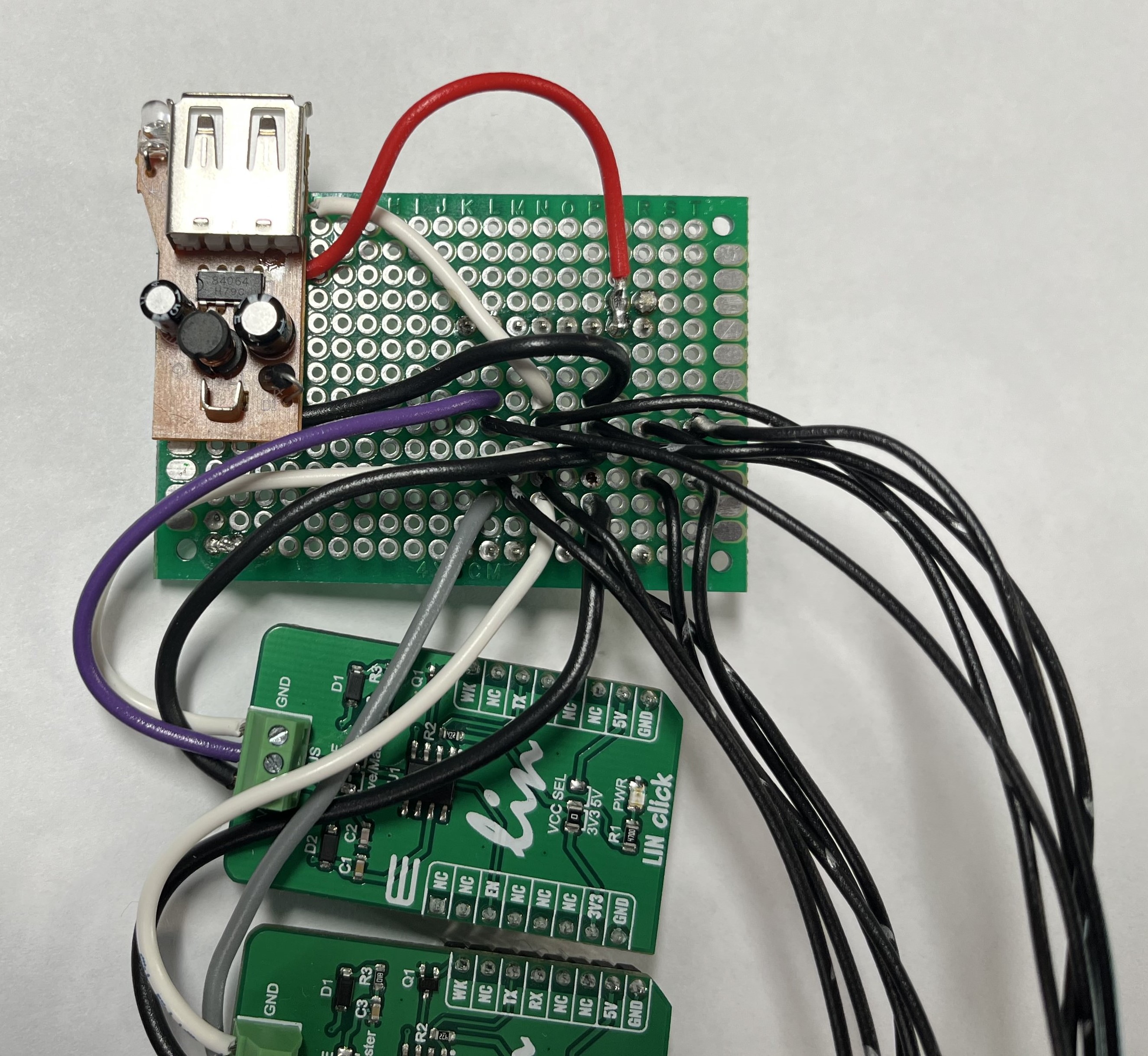
Step 3: Take apart your dollar store car charger
If using the ATA663254, you can skip this step. Otherwise, you will need to take apart your car charger and solder wires for 12 V, 5V, and ground to it.
Step 4: Prepare the Toyota connectors and wires
Remove wires from your Toyota connectors. You’ll need an extraction tool or a perfectly sized pin to get them out, and these connectors are very finicky and easy to break. I would suggest buying a second set of connectors because they’re cheap.
You will only need 10 wires total. Label 2 wires each as:
- 12V
- Ground
- LIN
- Illumination+
- Illumination-
Don’t insert them back into the connectors yet. It’s easier to solder them first.
Step 5: Solder everything together on the proto board
The best way I found to set up the proto board is by soldering pins to it so that it takes up the 3rd click slot on the shield. This way, you can keep everything attached to the Arduino rather than having to find another place to mount the proto board.
Some connections can be made without the board, but having a central connection area simplifies things a bit.
You want to connect the following:
- All grounds, including the Arduino ground, both LIN grounds, the car charger ground, and ground from both connectors
- All 12V, including the Arduino 12V, both LIN 12V, the car charger 12V, and 12V from both connectors
- The car charger 5V to a 5V pin on the Arduino
The rest of the connections can be made directly, but connecting them through the proto board allows for cleaner wiring:
- Illumination+ and Illumination- from both connectors (these are direct and do not pass through the Arduino)
- LIN from the car connector to the Responder LIN click
- LIN from the panel connector to the Commander LIN click
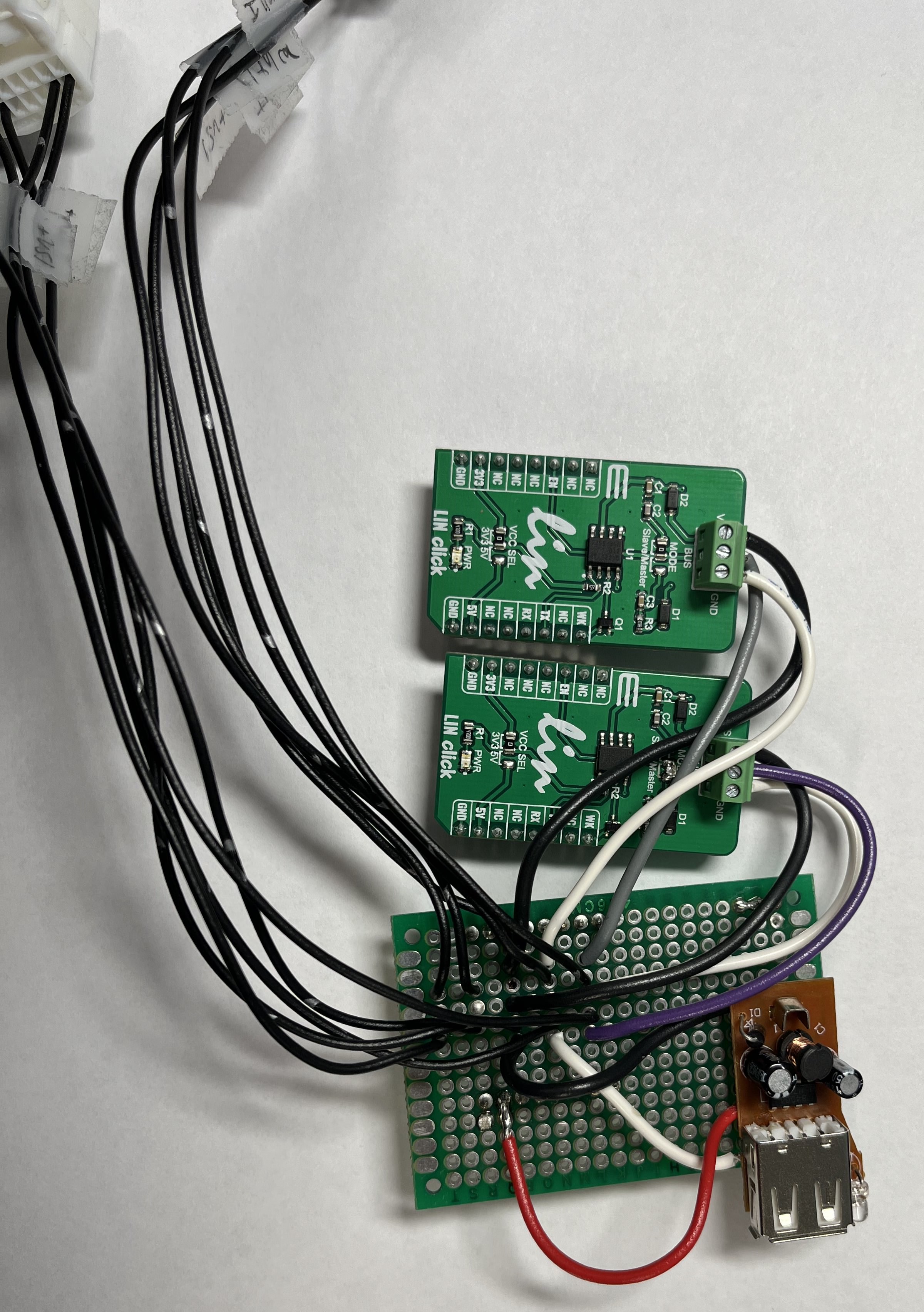
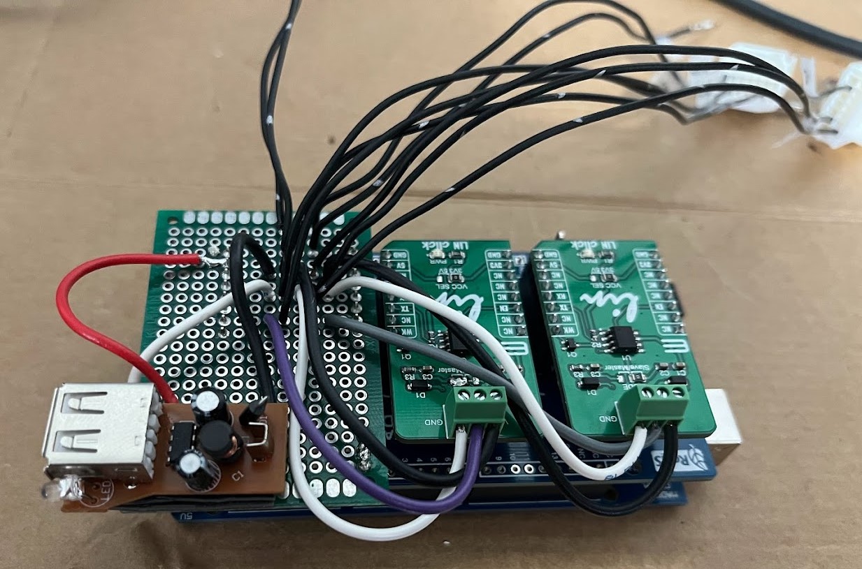
Then all you have to do to build it is plug the clicks and proto board into the click shield and insert the appropriate wires into the screw terminals on the LIN clicks.
Step 6: Test every connection with your multimeter
Remember, you’re dealing with your car’s electrical system. Electrical problems in cars, especially newer ones, can be very expensive to fix, so it’s best to be safe. Make sure that you have continuity between all of your connections and that you have no shorts. If you have a short, you will need to find it and fix it before continuing.
Step 7: Flash the Arduino
Clone jbschooley/ToyotaLinInterceptor and push it to your Arduino. I use CLion with the PlatformIO plugin. You may be able to use another IDE, but I haven’t tried it.
Step 8: Plug it in and test it!
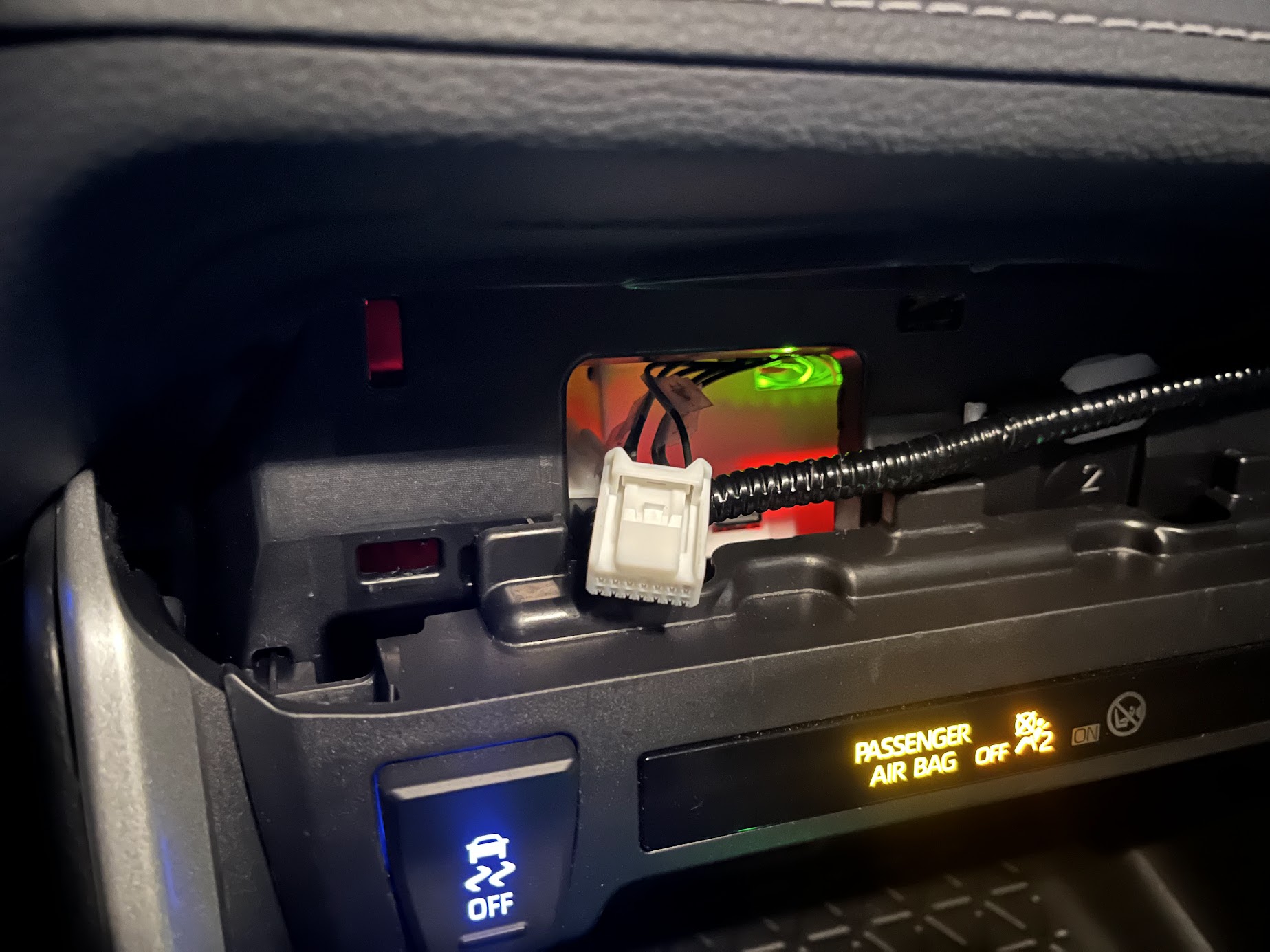
Remove the climate control panel. Unplug it from the car and attach the interceptor between the panel and the car. Plug it back in and turn the car on. If everything is working, you should see the panel light up and the climate control buttons should work. By default, there won’t be a preset configured, so hold down the S-Mode button for a second, then turn the driver’s temperature knob to the right to set a preset.
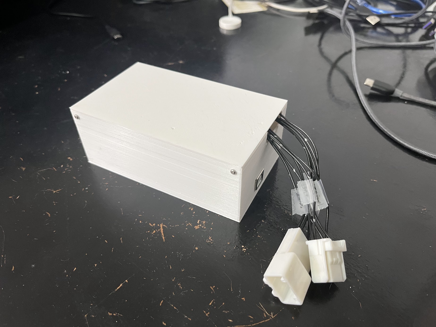
If everything works, install it behind the dash. You may want to 3D print a case so it doesn’t touch anything it’s not supposed to and short itself out. This case barely fits behind the dash, and it was a pain to get it in, but it does fit.
Software
The software is written in C++ and uses the Arduino framework. I’ve tried to keep things as simple as possible and keep things modular so that it’s easy to add new features. You’ll notice that all code is kept in .h files. No, this isn’t best practice, but it made development a bit easier and the difference in compile time by keeping implementation code in .cpp files was negligible.
Button.h- handles state for a button on the climate control panel and triggers actions on press, hold, and releaseMenu.h- holding the S-Mode button will replace the driver’s temperature display with a preset menu. Turning the driver’s temperature knob will cycle between presets, and the preset will be saved when the button is released. Presets are displayed as L1, L2, etc. on the display. (Why L#? Because I had to pick from the text the panel was configured to display, and I figured those were the least likely to be seen during normal operation. I think the car can display up to L32.) If new presets are added, increment thenumPresetsconstant.Toggle.h- holding the Eco button will toggle the preset on and off. The display will toggle between the preset number andOFFwhen the button is held.OffButton.h- turns off the rear defroster when the Off button is pressed.
LINController.h- handles low-level sending and receiving messages on the LIN busHandler.h- handles state for reading and writing messages on the LIN bus and ensures received messages are validated before being processed.CarHandler.h- handles reading, forwarding, and responding to messages from the carPanelHandler.h- handles sending data and requests and responding to messages from the panel
DataStore.h- stores data received from the car and the panel and handles reading and writing to EEPROMModifier.h- used to modify intercepted data before it’s forwarded. This includes modifying temperature, fan speed, and buttons pressed.Preset.h- defines how a preset is appliedPresetMaxDefrost.h- turns on front and rear defrosters, sets fan speed to high, sets temperature to max, and turns off eco mode and S-Mode
PresetController.h- handles applying the correct presets. This is where you can add new presets.Timer.h- a debug timer that can be used to measure how long it takes to process a message. It’s not used in the final code, but it’s useful for debugging.Logger.h- a debug logger that can be used to log messages to the USB serial port. Loggers are disabled unless necessary for debugging because log output is incredibly slow and causes the Arduino to miss messages on the LIN bus.
I’ve tried my best to keep things organized, but my code is definitely not perfect. I’m open to suggestions and pull requests.
More detailed documentation can be found in the source code.
Possible Improvements
This project is far from perfect, and there are some things I would like to improve in the future.
I would like to be able to have the preset always activated if I use the remote starter to start the car. It’s easy to forget to turn it on before parking for the night and then it doesn’t work in the morning. I probed every wire in the remote starter connector and couldn’t find anything that would indicate whether the car was started with the remote starter or not, but there’s got to be a way to do it.
One possibility is that messages are sent over the CAN bus when the remote starter is used. Reading these messages would require a CAN transceiver, and there currently isn’t space on the click shield unless I want to reposition the proto board and rewire everything. I would also have to tap into CAN wires somewhere, which means I’d have to buy more connectors. I’m not sure if it’s worth it.
I could also wire up the other output from my car’s tracking device to the Arduino and have it watch for a pulse on that. For that to work, though, I’d have to remember to trigger it every time I use the remote starter. It wouldn’t be able to be triggered by the output to the remote starter itself because the Arduino wouldn’t yet have power. I could maybe integrate a separate low-power controller that only watches for the remote starter output and triggers the Arduino once it’s powered on.
I would also like to build a custom board rather than using the click shields. As it is, the wiring is a bit messy and the whole thing barely fits behind the dash. I could use this unofficial Arduino Mega 2560 Pro and design a custom PCB around it to handle the wiring and power. I’ve never designed a PCB before, though, and I’m not sure I want to spend hundreds of dollars ordering prototypes that I’ll definitely get wrong the first few times.
A Little Discussion About Security
I’m a cybersecurity student, so I’m always thinking about security.
It’s taken for granted these days that most of our day-to-day activity on the Internet is done securely. Most modern websites are configured with HTTPS, which uses the TLS protocol to encrypt our data as it is transmitted between the client and the server, ensuring that nobody can see what’s being sent. The server sends a certificate to the client to prove that it is who it says it is, and the client verifies the certificate (and shows a big scary warning if it doesn’t check out). You then use a username and password (and hopefully two-factor authentication) to prove that you are who you say you are. This way, when you’re buying something on Amazon, nobody can see what you’re buying, you know you’re giving your credit card information to Amazon, and Amazon knows that you’re the one giving them your credit card information.
Embedded networks are a different story. They use different protocols, some of which have defined standards for encryption and authentication, but many of which do not. Networks with very limited bandwidth are designed to use the bandwidth they have as efficiently as possible, and encryption and authentication are often not a priority, so data is left to be transmitted in the clear. This is the case with the LIN bus. There is no encryption or authentication, so anyone with access to the bus can see and modify the data being transmitted. There is a checksum to ensure integrity, but the checksum can be generated by anyone with access to the data. Because of this, once I have access to the LIN bus, I can do whatever I want with it.
Why would Toyota leave it open like this? The answer is risk. Risk, according to NIST, is “the extent to which an entity is threatened by a potential circumstance or event;” in other words, the likelihood that something bad will happen and how bad it will be if it does. For Internet traffic involving personal data, like the Amazon example mentioned above, the risk is very high. Without encryption and authentication, a malicious actor could watch you make a purchase and then steal your credit card data, or pretend to be Amazon and steal your username and password. They would then have easy access to your money, and they’d know where your stuff is being shipped so they could rob you once it’s delivered. The risk is high enough that it’s worth the cost of implementing encryption and authentication.
But for the climate control panel, the risk is low. The data being transmitted is not sensitive, and the worst that could happen is that a bad actor could blast cold air in your face in the middle of winter or disable your climate control system (although they could do that by just unplugging the panel). Maybe if they had something out for you in particular they could short circuit the connection and break your climate system. Doing any of these, however, would require physical access to the car. It’s already secured with a key, and if they’re able to bypass the car’s physical security measures get into the car there’s so many other things they could do to ruin your day. The cost of implementing additional encryption and authentication on the LIN bus is high, so it’s not worth it. (From Toyota’s perspective, though, this project is a risk they may not have considered–it uses this lack of security to give my car a feature that is usually reserved for more expensive trim levels.)
This extends to most of the embedded networks in the vehicle. There are a few, however, where the risk would be considerable enough that it would be worth the cost of implementing security measures. For example, the bus that connects to the lock switch and the door lock actuators, or the bus that connects ECUs to each other. If a bad actor could get access to this bus, they could lock you out of your car or unlock it and steal your stuff, or steal the whole car.
Another important one is the CAN bus that connects to the lane keep assist and radar cruise system. I use a Comma.ai device, which intercepts this bus to massively improve upon my car’s built-in lane keep assist and radar cruise control to the point where I can drive hands-free on the highway. As someone who gets worn out by long road trips, being able to use these commands is awesome, but it’s a huge security risk. If a bad actor could get access to this bus, they could spoof the radar and lane keep assist systems to unexpectedly slam on the gas or brakes or steer the car off the road. Imagine a hitman who installs a little box with a CAN interceptor and a cellular radio under the lane keep camera cover. They could then take out their target by remotely taking over their car and driving it off a cliff. You might not be interesting enough to have a hit put out on you, but if you’re a celebrity or a politician, this is a real risk.
Toyota clearly does not like this because in new model years they’ve started locking this down with a protocol called Autosar SecOC. While this does not encrypt messages, it authenticates messages with a checksum that is generated using a key that is unique to each car. This prevents malicious actors from taking control of a car while it’s driving, which is a very good thing. However, it has been a major thorn in Openpilot’s side as it isn’t able to control new model year cars, and talented developers have been working to crack it for the last 2 years and have not yet succeeded. Toyota also makes more money this way because they’re able to convince people to buy a more expensive trim with their Teammate system instead of using a Comma device. They know Comma exists and secured the bus because leaving it open was a risk to both driver safety and their bottom line.
Personally, I would like to see this cracked, but in a way that only the car’s owner can sign the checksum so that malicious actors can’t take control of a car while it’s driving. For example, if the owner could get access to the key as it’s being distributed through the CAN network, they could use it to sign the checksum. This would allow them to use Openpilot, but it would prevent malicious actors from taking control of the car while it’s driving. If a vehicle manufacturer wanted to support 3rd party solutions, they could provide a way for the owner to be given the key if they sign a release of liability over the driver assistance systems, similar to unlocking the bootloader on a phone.
Some other car manufacturers secure those messages as well, including all Teslas and (I think) some GM vehicles. I’m not sure how they implement it. Most other manufacturers, however, do not. If a car is on this list it’s a reasonable assumption that authentication is not implemented on the CAN bus.
Conclusion
I had a lot of fun working on this project. I probably would have spent less time if I just manned up and went outside early to start the car or scrape ice, but it was a great learning experience, and I learned a lot about embedded systems and the LIN bus. I’m always happy to answer questions, so feel free to ask in the comments.